During the design process, we wanted to make Geronimo’s arm
as simple and as elegant as possible. Because of this, we decided that the arm
would consist of two parts:
- A parallel linkage oriented vertically so that the arms height could be adjusted
- A horizontally mounted arm that could rotate 180 degrees in order to account for the horizontal offset created by the parallel linkage
Initial prototype of Geronimo's arm.
Initially, we thought that we could use servo motors to
control the arm. Our first prototype proved that these movement patterns were
in fact possible using servo motors. However, there were some stability issues
with various components of the arm. Additionally, the catchment plate that the
pets were supposed to stick to changed orientation throughout the process,
which limited the arms functionality.
A second prototype was made, with new servo mounts for the
parallel linkage and a bracket for the horizontal arm. In order to maintain the
desired geometry of the catchment plate, a fourth servo was added to the end of
the horizontal arm.
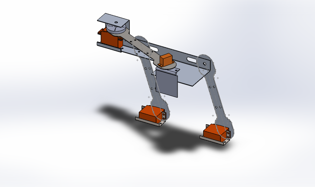
Second prototype of Geronimo's Arm.
After the arms performance at time trials, we were concerned
that the servo motors were not powerful enough to remove the pets from the arm
using our chopping motion. A video of
this testing phase can be seen below.
Video showing second prototype's inability to remove pet.
In addition, the two servo motors controlling the parallel
linkage were not able to be precisely calibrated, and so one was always a few
degrees off from the other. Because of this, the servos would fight each other.
Eventually one of the servos “won”, and we had a servo fire.
The problems with the arm caused us to fall behind schedule,
and at this point, we decided that it would be in our best interest to start
from scratch and make our own servo motors. The arm rebuilt took Dave and I two
days, and involved us re-making the arm components to accommodate larger
motors, gear systems, and potentiometers.

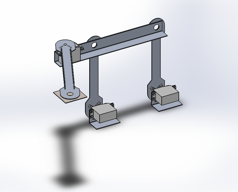
Solid model of final arm design.
The day before the competition, we began to have problems
removing pets from the arm once more. We determined that the motor powering the
horizontal arm was not strong enough, and so we opted for a stronger motor.
However, when I was mounting the small gear to the motor we chose—something I
had done with every previous motor—I managed to break the motor. In the hours
that followed, the team searched for a replacement motor that would be strong
enough to accomplish the chopping motion we wanted. This set us back even
further.
We finally found a motor that suited our needs, and mounted
it to the arm at 10:30pm, the night before the competition.
The servos that we made featured the following:
- 3D printed bearings, to increase stability of the arms
- Potentiometers that rotated with the arms
- High torque motors
- Gear ratios of 3:1 for increased torque
The final arm design featured the following:
- An all-aluminum parallel linkage
- An aluminum horizontal arm
- A steel catchment plate attached via a zinc-coated steel hinge
- A magnetic sensor attached to the steel pin of the hinge to determine when the arm picked up a pet.
The final arm can be seen below.

Catchment plate and small servo mounted to end of horizontal arm.

Custom servo set-up driving horizontal arm. Nicknamed "Fat Bastard" by the team.

Custom servo set-up that drove the parallel linkage. Nicknamed "Satan" by the team.

Final arm design mounted on Geronimo.
Author: Josh Smith
No comments:
Post a Comment