Tuesday, August 11, 2015

Geronimo’s Drive System

The first system that was prototyped for Geronimo was the drive system. Early on, we knew that we wanted the drive system to be simple and powerful. We decided on large wheels and a large gear ratio (7:1) to ensure that the drive system would be able to drive Geronimo up the incline on the playing surface. Our initial prototype featured:

  •           Large gears (70 teeth), cut from acrylic on the laser cutter
  •          Small gears (10 teeth), cut from aluminum on the water jet cutter
  •         Wheels (6” diameter), cut from wood on the water jet cutter
  •          Barber-Coleman geared motors
  •          Tires cut from inner tube
  •         A large, 3/8” thick main axle
  •           Aluminum gear plates to aid in alignment


The prototyped version of the drive system can be seen below.
Geronimo with prototyped drive system.


While the prototyped drive system functioned, we found that there were alignment problems with the wheels. In the second and final iteration of the drive system, we added 3D printed bearings. These bearing fit tightly into the center holes of the wheels and large gears, and loosely fit onto the primary axle. The bearings removed the side to side play of the wheels while still allowing them to rotate about the axle. Additionally, self-fusing tape was used as tire material in the final version of the drive system. The final version of the drive system can be seen below.
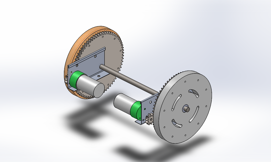
Solid model of final drive system.

Side view of final drive system.


Author: Josh Smith

Geronimo’s Suspension System

A major part of Geronimo’s original strategy involved jumping down from the upper level of the course to the lower level in order to bypass the wall of fire. Unfortunately, last minute setbacks prevented us from making it to the upper level. We were, however, still able to utilize the suspension system and jump from the ramp down into the safety zone.

The original concept for Geronimo’s suspension system can be seen below. The sled was designed to absorb the majority of the impact from the resulting drop, while the spring system (consisting of rubber bands) was intended to absorb the rest.

Concept of suspension system, minus hardware and elastics.


In addition to absorbing impact, the sled was also intended to act as the forward pivot point in the drive system, thereby simplifying steering operations. As such, the QRD’s used for tape following were placed in the sled, so as to put as much distance between them and the motors as possible.
Initial tests showed that the suspension system was fundamentally flawed, as Geronimo would flip forward following his jump. This can be seen in the following video.

Video shot showing Geronimo flipping.


After analyzing the footage above, we determined that the problem was that the sled was not rigidly attached to the rest of the suspension system, thereby allowing Geronimo to rotate about the sled following the jump. This problem was solved by replacing the foremost axle with M6 hardware, which held the sled more rigidly in place.

Unpowered test ran to test updated suspension system.


The final version of the suspension system can be seen in the following figures.  
Geronimo's internals, including the elastics that make up part of the suspension system.

Fully assembled sled.

Final sled mounting.

Author: Josh Smith

Monday, August 10, 2015

Testing out the mobility of Geronimo
We have chosen to upgrade the robot's chassis and so I started working on this. During the last week many issues have risen with regard to the arm; the servos blew, we had to built custom servos, power to rip of the pets were not enough, and more. I focused more on the chassis, mobility, wiring, and software so while my team handles the arm I started to upgrade the robot and make sure my part of the work is done.

IR, QRD, Line following, magnetic sensor, have all been tested and all work. In the mean time i also wrote the master code which right now can run a dry run (we simulate the sensors to see how the system reponds) since we did not have the time to run the actual field so many times since many teams were lining up for it. It worked very well but we are still unsure on how it will work.

The blue geronimo was done by water jet cutting the name and putting blue tape on the inside an idea i randomly had and it turned out to be a great way to bring some cheap flare to the robot.

We got the QRD to work with some error, we also got IR following to work as posted in another video.

The current guts of our robot.

Week 3, things staring to heat up.

I start to focus on the wiring of the boards; initially we wanted to make a series of trays for TINAH and the circuits but after some arguments I convinced my team mates to use the chassis of the robot to house all the wiring and have a hinged cover. And so I started wiring things all day and we  came across a rather big problem; the TINAH would not fit properly within the cover and would be hard to access. So we decided to have the TINAH halfway into the chassis with half of it coming out of the cover.

Also as can be seen we started working on fixing our drive system. To do this we made bearings and better wheels and tires to remove some slipping problems. Things are going well at this point and we are back on track.

During this week I learned a lot of soldering skills and I am starting to love what I use to hate. I also done some programming for the line following.

Saturday, August 8, 2015

Along with the water jet machine, we had access to a laser cutter. It enabled us to make very high-precision parts with lighweight plastic materials like plexiglass and Delrin. In the video below, I demonstrate how it cuts out a small gear for our drive system: